6.7 Pneumatic components
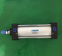
Pneumatic components are made of Japanese SMC, installed on the basic frame and connected to the factory gas line. A filter regulator with a pressure gauge and a pressure control device are installed in front of the valve. A hose with the necessary threaded connection is provided and used as a connecting line between the valve and the cylinder.
The air used in the pneumatic system should be clean, dry compressed air. The water separator in the air path must be frequently observed and drained in time. The filter element in the water separator should be kept clean and cleaned regularly.
The factory gas source pressure is required to be no less than 0.6Mpa. The gas source is first connected to the gas source processing unit of this system, and then enters the pneumatic pipeline after water separation and air filtering. There is a water drain button at the bottom of the water separation and air filter. The water in the cup should be drained regularly, and the filter element should be kept clean and cleaned or replaced when necessary. The set pressure of the pressure reducing valve, that is, the working pressure of the system, is 0.55 MPa.
The gas lines and pipes are all protected, and the gas valve exhaust is equipped with a muffler.

6.8 Control cabinet
Covering control power supply, control device, emergency stop circuit, main switch, Siemens PLC (S7-1200), Advantech industrial computer, UPS, alarm system, Symbol barcode scanner, constant temperature air conditioner.
6.9 Motor Drive Control System
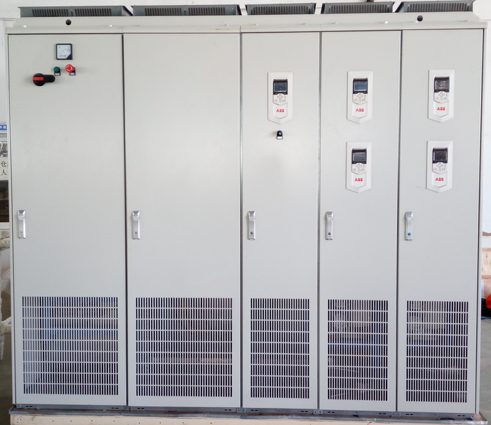
Power grid connection ------ 3-phase power supply voltage: U31N=380V±10%; frequency: 50Hz; power factor: COSØ1=0.97.
Efficiency-----at rated power greater than 98 percent; heat loss less than 300W.
Torque control accuracy-----Torque step rise time:
Open loop <2ms (at="" rated="">
Closed loop <2ms (at="" rated="">

6.10 Driver's operating panel
The operator's operating panel is placed within the operator's reach when the vehicle is in the test position.
6.11 Test bench display
32-inch driver information LCD display, column mounted, placed 2m in front of the driver's seat and 1m to the left when the vehicle is measured, used to instruct the driver to operate according to the prompt interface.
6.12 Red, yellow and green traffic lights
At the traffic light in front of the test bench, the red light indicates an abnormality, the yellow light indicates that it is being tested, and the green light indicates that you can enter the testing station.
6.13 ECU Communication
Matching cable, with OBDⅡ connector, CAN bus detection software, all necessary information about vehicle model ECU. ECU communication protocol, ECU diagnostic protocol
6.14 Control system software
1) Based on Window7 Chinese operating system
2) Chinese software, Chinese operating interface
3) Parameter setting interface
4) Real-time test process monitoring interface
5) Calibration interface
6) Error message prompt
7) Access database, which can be queried in various ways, can store the inspection data of no less than 10,000 vehicles.
6.15 Exhaust extraction and collection tray
Used to discharge exhaust gas and collect liquid, exhaust condensate, coolant, etc.
Related News
- How does the dynamic four wheel aligner avoid communication interference?
- Introduction to vehicle electrical inspection
- How to choose a good pass four wheel aligner
- What is the assembly line
- The important role of the through four wheel aligner
- The four main points of 3D laser four wheel aligner maintenance
- Working principle of electric chassis dynamometer
- Vehicle off-line comprehensive diagnostic equipment
- How to choose a good dynamic four wheel aligner
- Precautions for selecting a non-contact four-wheel aligner
- Introduction to technical parameters of comprehensive drum test bench
- Scope of supply of comprehensive drum test bench equipment
- Instructions for use of the contact type dynamic surface measurement 4 wheel alignment instrument (I)
- Instructions for use of the contact type dynamic surface measurement 4 wheel alignment instrument (2)
- Basic structure and working principle of contact type dynamic surface measurement 4 wheel alignment instrument (I)
- Basic structure and working principle of contact type dynamic surface measurement 4 wheel alignment instrument (2)
- Contact type dynamic surface measurement 4 wheel alignment instrument test process
- Installation and calibration preparation of 4-wheel alignment instrument for contact dynamic surface measurement
- Contact type dynamic surface measurement 4 wheel alignment instrument wheelbase adjustment
- Safe use and precautions of contact type dynamic surface measurement 4 wheel alignment instrument
