3. Basic structure and working principle
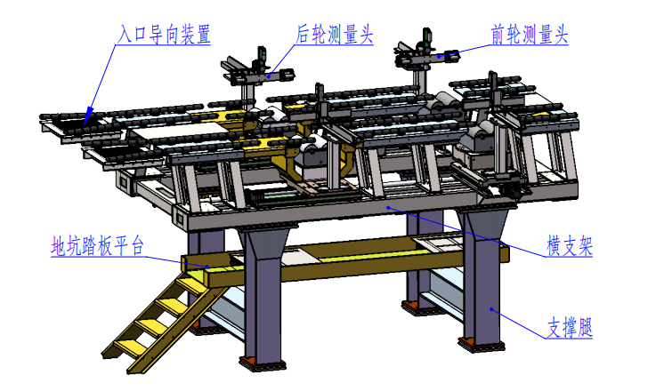
The test bench consists of the main frame, roller system, detection head system, wheelbase adjustment system, centering device, motor drive control system, signal acquisition, data processing, PLC control system and display part. The details are as follows:
1. Equipment as a whole
1. Equipment main frame:
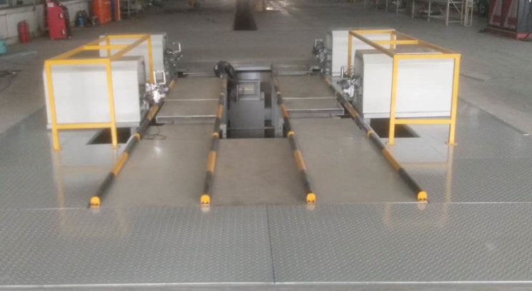
The main frame of the equipment is made of steel structure, supported by 4 supporting legs, and all the components of the equipment are installed on the frame structure.
The foundation pit depth is 2700mm---3100mm.
The supporting legs are connected to the main frame through horizontal adjustment bolts, which are used to adjust the level of the equipment frame.
The frame structure provides installation lifting points.
The bottom parts of the equipment frame support legs will be welded together with the embedded steel structure (made by the user) to ensure the smooth operation of the equipment.

Driving channel
The left and right lanes are used for vehicle entry\/exit. They can be adjusted to accommodate changes in wheelbase. The lanes are specially designed to ensure that trench operators have maximum adjustment space.
The load-bearing capacity is greater than or equal to 1,000 kg\/wheel. Guide rollers are installed on the side to prevent the vehicle from deviating when driving on the test bench.
To meet the requirements of different vehicle models, a bell-mouth guide device is installed at the entrance.

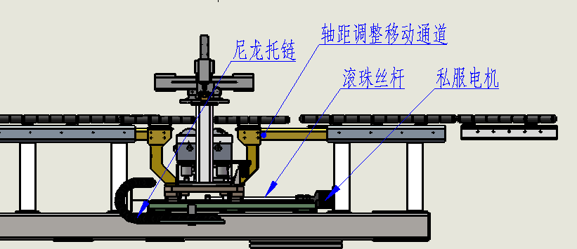
Wheelbase adjustment device

Automatic wheelbase adjustment allows the driver to select the correct wheelbase for the vehicle being tested.
Inspector operation panel
Under the trench or in the control cabinet.
Start control and measuring cycles (e.g. wheelbase adjustment, centering, measuring and adjustment, etc.).
Steering wheel balancer

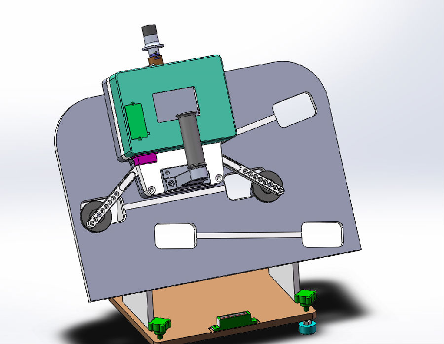
Equipped with 1 set of steering wheel balancer: used to measure the steering wheel angle.4 wheel alignmentThe control system communicates wirelessly. The steering wheel angle value is transmitted to the 4-wheel alignment instrument industrial control computer for toe adjustment correction to ensure that the steering wheel angle is zero when the car is driving in a straight line. It is suitable for mainstream car steering wheels and meets the safety requirements of airbag steering wheels. The steering wheel balancer has a measurement range of greater than or equal to ±5 degrees, a resolution of 0.1 degrees, easy clamping, simple operation, and a total weight of less than or equal to 3kg. The steering wheel balancer has the following functions and configurations:
(a) The steering wheel balancer has a display screen with a digital real-time display of the steering wheel inclination angle.
(b) The steering wheel balancer is equipped with a buzzer reminder.
(c) Equipped with 1 set of steering wheel balancer charging device.
(d) Provide 1 set of power cables that can be quickly plugged in for emergency power supply of the steering wheel balancer.
(e) Equipped with 1 set of steering wheel balancer calibrator.
(f) The steering wheel balancer is equipped with a telescopic top rod fixing device to ensure that it can be fixed on the front windshield during the measurement process and is easy to install and disassemble.
(g) The housing is made of strong and durable material, suitable for industrial environment.
(h) With extended OBD interface, supports CAN communication.
Related News
- How does the dynamic four wheel aligner avoid communication interference?
- Introduction to vehicle electrical inspection
- How to choose a good pass four wheel aligner
- What is the assembly line
- The important role of the through four wheel aligner
- The four main points of 3D laser four wheel aligner maintenance
- Working principle of electric chassis dynamometer
- Vehicle off-line comprehensive diagnostic equipment
- How to choose a good dynamic four wheel aligner
- Precautions for selecting a non-contact four-wheel aligner
- Basic structure and working principle of contact type dynamic surface measurement 4 wheel alignment instrument (2)
- Contact type dynamic surface measurement 4 wheel alignment instrument test process
- Installation and calibration preparation of 4-wheel alignment instrument for contact dynamic surface measurement
- Contact type dynamic surface measurement 4 wheel alignment instrument wheelbase adjustment
- Safe use and precautions of contact type dynamic surface measurement 4 wheel alignment instrument
- Introduction to manual operation and zeroing of 4-wheel aligner
- Contact type dynamic surface measurement 4 wheel alignment instrument toe-in, camber, caster detection
- 4. Detection of the maximum turning angle of the wheel aligner
- 4. Kingpin inclination detection of wheel alignment instrument
- Introduction to the inspection method of 3D laser 4-wheel alignment
