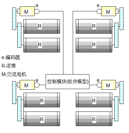
3. Mechanical structure

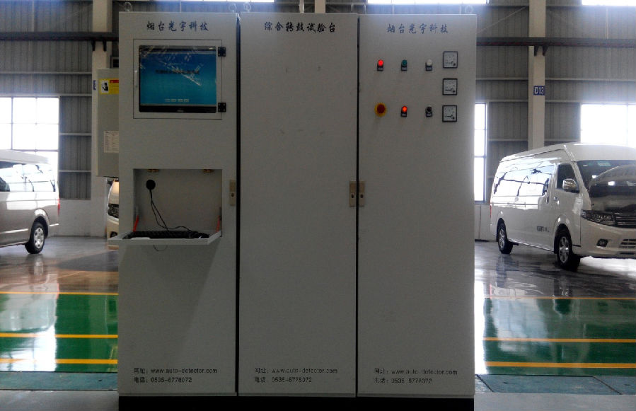
4. Electronic control part
4.1, Equipment data processing, networked industrial PC computer with keyboard, using Windows7 operating system. The test bench computer uses SQL database, which can store at least 1,000,000 vehicle test data results. The test data result database is open to users, and the test data can be easily and quickly queried. After the barcode scanner reads the barcode, it automatically calls out the test parameters that match the model; the barcode can also be entered through the computer keyboard. The computer is equipped with an online UPS.
4.2, Electric control cabinet operation panel: equipped with emergency stop button, emergency stop indicator light, fault indicator light (optional).
4.3, equipped with 1 set of wireless ECU communication ECU-V3 communicator: used for diagnosis and testing of vehicle ECU, the ECU communication interface of all models is OBDII and the same.

5.Electrical structure

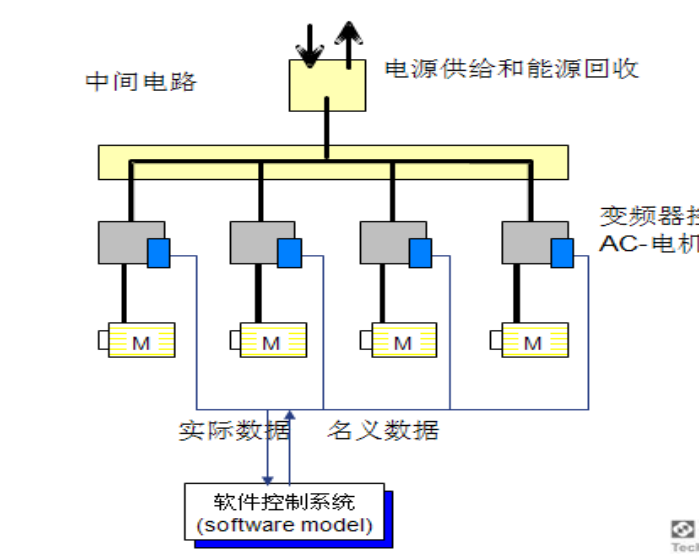
The main drive motor consists of a driver with 4-quadrant closed-loop control and digital encoder feedback.
Frequency conversion motor: 45kW4, duty S44 quadrant drive consists of 4 power units, 2 of which are connected in parallel as active rectifiers on the grid side, and the other 2 are connected in parallel as motor side drives. It can perfectly complete the two-way energy exchange between the grid and the motor. The power factor is close to 1, and the system is not affected by grid fluctuations. Each power unit output side as the motor side drive is equipped with a current-sharing output reactor. In addition to the current-sharing function, it can also effectively reduce the motor port du\/dt and bearing current, filter out high-frequency harmonics, thereby reducing the motor magnetic noise, protecting insulation, and extending the life of the motor. Each 4-quadrant SPMD4403 drive input end is equipped with a high-frequency filter unit to ensure that when the system is in the feedback state, it can feed back to the grid with a pure sine wave without polluting the grid. Each 4-quadrant drive is equipped with a 500A circuit breaker as the incoming line switch, and a varistor is set as the overvoltage absorption circuit. With the upper control interface, the transmission control unit provides a communication port with a maximum rate of 12M\/B
Related News
- How does the dynamic four wheel aligner avoid communication interference?
- Introduction to vehicle electrical inspection
- How to choose a good pass four wheel aligner
- What is the assembly line
- The important role of the through four wheel aligner
- The four main points of 3D laser four wheel aligner maintenance
- Working principle of electric chassis dynamometer
- Vehicle off-line comprehensive diagnostic equipment
- How to choose a good dynamic four wheel aligner
- Precautions for selecting a non-contact four-wheel aligner
- What is the difference between a static 4-wheel alignment instrument in a repair shop and a dynamic surface measurement 4-wheel alignment instrument in a car factory?
- Analysis of relevant matters of 3D laser 4-wheel alignment
- Analysis of the principles and advantages of 3D laser 4-wheel alignment
- 3D laser 4 wheel alignment installation and maintenance matters
- Introduction to some misunderstandings in 4-wheel alignment
- What aspects should be considered when choosing a 3D laser 4-wheel aligner
- Innovation of non-contact 4-wheel aligner
- The manufacturer of through-type 4-wheel alignment instrument shares the main detection methods of 4-wheel alignment instrument
- What is the relationship between the through-type 4-wheel alignment and the deviation of the car?
- Under what circumstances is it necessary to use a dynamic 4-wheel alignment instrument for 4-wheel alignment?
