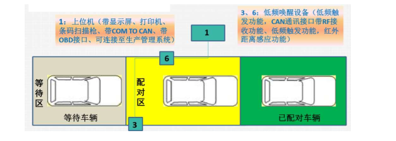
Tire pressure equipment operating instructions
1. The tire pressure device 3 sends a right front wheel wake-up command when detecting the vehicle, 3 receives the RF information and transmits it to the upper computer through the CAN;
2. The tire pressure device 6 sends a left front wheel wake-up command when detecting the vehicle, 6 receives the LF information and transmits it to the upper computer through the CAN;
3. When the tire pressure device 3 detects the vehicle again, it sends a right rear wheel wake-up command, 3 receives the RR information and transmits it to the host computer through the CAN;
4. When the tire pressure device 6 detects the vehicle again, it sends a left rear wheel wake-up command, 6 receives the LR information and transmits it to the upper computer through the CAN;
5. The paired vehicle stops at the parking line;
6. Connect OBD and scan VIN code;
7. The host computer sends the sensor ID to the receiving module on the vehicle through the CAN;
8. The host computer commands 3 and 6 reset, waiting to detect the next car.

Related Industry Knowledge
- ADAS advanced auxiliary driving calibration equipment calibration purpose
- What is the function of the high-speed ABS brake test rig?
- Introduction to non-contact four-wheel aligner
- Main configuration of ABS brake table
- Safety inspection project
- Comprehensive drum test bench product introduction
- Non-contact four wheel aligner operating procedures
- Application of laser measurement technology in automobile four wheel aligner
- Dynamic four wheel aligners have formed a trend
- How to maintain the dynamic four wheel aligner
- Why is ADAS advanced driver assistance calibration equipment so important to driving?
- What are the benefits of using a non-contact 4 wheel alignment
- What is the role of 3D laser 4 wheel alignment in the automotive industry?
- Tips for 4-wheel alignment using a dynamic 4-wheel aligner
- What are the common tools for comprehensive diagnostic equipment of vehicle off-line?
- Overview of Non-Contact 4-Wheel Alignment
